![]()
NetMaster is
 Explore Explore |
 Monitor Monitor |

 Explore Network Entities
Examining a network node
Each node in an ATM network has both input and output ports, which indicate the connections from the node to other nodes in the network. NetMaster plans the presentation using a set of standard graphical techniques: camera zooming, enlarging the selected node, and cutting the node open to reveal its port structure and connectivities to other nodes.


Examining a different node
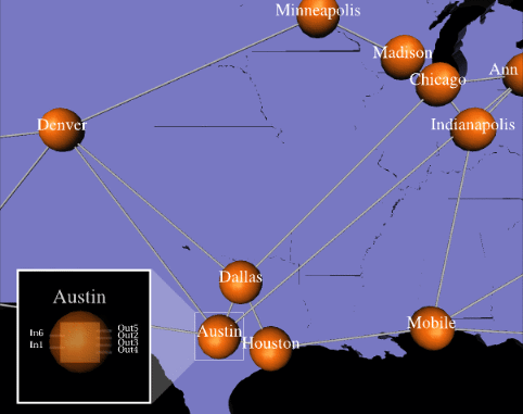
The goal of our research is to design effective presentations for different tasks in different situations. In this case, the same task of exploring a different node's internal structure is handled differently by the system because of the node's surroundings. Instead of enlarging the selected node, the node is associated with an inset window to show its internal structures. This avoids the possible confusion the could result if the node were enlarged and overlapped with the nodes nearby.


Examining a physical link
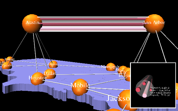
This picture presents a physical link and its internal structure. In this situation, the system designs the presentation such that the selected link (between the node Austin and Ann Arbor) is enlarged and separated from the rest of the network, and then is cut open to reveal the internal objects inside it. The internal objects within a physical link are called virtual links. Each virtual link has its own capacity and utilization. In the displayed picture, the capacity of the virtual link is encoded as the diameter of the cylinder that represents the virtual link. The small inset at the lower right corner gives even lower-level detail information about a selected virtual link segment within the link. The information displayed in the inset includes the source and destination of the virtual link segment, and its capacities.

 Monitor Traffic
Monitoring link traffic
There are three classes of traffic inside an ATM network. NetMaster uses three different colors to encode the three traffic classes as shown in the legend. The traffic capacity of the link is represented by the full length of the link, while the stacked bars represented the current utilization of the link.One of the goals of our system is to efficiently integrate new information into existing displays. In this picture, NetMaster places the stacked bar chart inside the selected link to take advantage of the space inside the link.

 |
 |