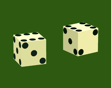
Figure 1-1. Communicative intent: show the dice
For centuries technological advancements have made the exact same presentation accessible to larger and larger groups of people. The continuing developments in mass communication technologies, starting with printing, engraving, photography, audio recording, film, video, broadcasting, and the most recent developments in electronic media have increased the potential size of an audience. Nevertheless, communication involves both intent and interpretation. The same presentation, viewed by several people, may be interpreted to mean different things, while different presentations may be interpreted to mean the same thing. To further complicate matters, none of these interpretations may be the one intended by the presenter.
With recent advances in computer technology, we may now embark upon a new phase of communication technology. New computer technologies will make the exact same meaning accessible to larger and larger groups of diverse people. These technologies will interact with users and create customized presentations with a specified communicative value in a form appropriate to a particular user in a particular situation. These systems will rely upon formalisms including those representing the intent of a communication (or communicative intent), the language or medium to be used, the audience and context of the communication, and the way in which the language is used to achieve communicative intent. Such systems will generate customized presentations, each designed to satisfy the same intent for a particular audience or a particular user in a specific situation. It is with this vision of the future that we began this work.
Our objective is to devise a scheme for effective visual communication. In this thesis we touch upon but a few issues involved in creating a complete system for visual communication. For our purposes we will treat a visual presentation as visual material that is designed to achieve communicative intent; that is, both convey what we want to communicate to our audience as well as elicit a desired action or interpretation. In this thesis we present a system to generate 3D technical illustrations automatically. We will define a visual language and an accompanying methodology for its use to both design and generate automatically 3D illustrations that fulfill a specified communicative intent. We will show how our approach is applied to generate different types of illustrations in different situations. We will also show our system’s extensibility and explain how mechanisms were introduced to handle overly constrained problems and several different types of interaction.
The goal of communication is to use language in such a way that an audience will interpret communicative material to mean what the communicator intended. Communicative intent describes the audience interpretation and consequent actions that the communicator wishes to elicit and is comprised of a set of communicative goals. We make the assumption of cooperating agents [Grice 69]; that is, we assume that the audience will attempt to interpret the communication correctly and that the communicator is communicating in order to invoke a particular interpretation. It is neither necessary nor desirable for the intent to specify all the objects and concepts used to satisfy the intent. Instead, the communicative intent provides a high-level description of what is to be communicated. The communicative goals drive the process that determines what information (set of objects and properties) to use to satisfy the intent. We use the term intent in the same spirit as [Grice 69] in his theorem of meaning:
“U meant something by x” is true if and
only if for some audience A,
U uttered x intending thereby:
(1) that A should produce response r
(2) that A should, at least partly on the basis of x,
think that U intended (1)
(3) that A should think that U intended (2)
(4) that A’s production of r should be based
(at least in part) on A’s thought that U intended
(1) (that is, on A’s fulfillment of (2))
(5) that A should think that U intended (4)
U thereby intended to communicate I (using x) and I is not simply a set of facts or some information, but encompasses all that U wishes to convey. Intent does not explicitly specify x, or the content and form of the communicative material. Though the intent is to indicate a fire, the communicative material may be designed to describe smoke. Similarly, if someone yells, “Fire!” and there is a fire, the communicative intent is most likely to warn people that a fire has broken out and some action should be taken.
The goal of communication is therefore to satisfy some communicative intent. This goal serves as a basis for evaluating the effectiveness of a communication. Suppose that U intends to communicate I1, I2, and I3 to A. If A interprets the communication to signify I1 and I2 but not I3, then the communication has failed in part. It is important to note as well that if A interprets the communication to signify I1, I2, I3, I4, I5, and I6, the effectiveness of the communication is also lessened. Even though I1, I2, and I3 were correctly communicated, A misinterpreted the intention of the communication by interpreting the communication to signify a superset. The effectiveness of a visual presentation is a function of how a viewer will interpret it. If the viewer's interpretation corresponds to the intent of the presentation, then we will deem the presentation effective, but we will evaluate the presentation’s effectiveness to decrease as the viewer’s interpretation deviates from the intent.
By using communicative intent as the method for specifying communicative material, the same information may be used to communicate different things. Consider the design of a picture showing a chameleon sitting on a leaf. If our intent in designing the picture is to communicate how well a chameleon blends in with its natural environment, the chameleon may be impossible to detect in the picture we generate. If our intent, however, is to communicate the location of that chameleon, we may highlight the chameleon so that it stands out and its location is clearly conveyed. Without a notion of intent, either implicit or explicit, a system cannot deliberately generate visual presentations, based on the same information, that have deliberately different semantic values and intended audience responses.
Computer graphics systems typically rely on human intervention for the design of a picture. The traditional input that specifies a computer-generated picture consists of a display list of all the objects to be depicted, a viewing model specifying the station and reference points for the eye and a rectangular subset of a projection plane, rendering algorithms, and a lighting model. The values assigned to these parameters affect the outcome of the picture, and thus its semantic value. Knowledge-based graphics systems differ from traditional graphics system in that they automatically generate some or all of this otherwise hand-made input for a graphics system.
We define an illustration to be a picture that is designed to fulfill a communicative intent, and whose function is to convey successfully this intent to its audience. We use the term communicative intent (or, simply, intent) to encompass the purpose, desired actions, and, in some part, the propositional content of the material to be communicated. Intent does not specify what objects will appear in the illustration, nor does it specify what styles will be used. These stylistic decisions are made to achieve intent during the illustration process. Examples of intent are to show an object’s position or instruct the user how that object is to be manipulated. Intent can be more complex; it may be more important to show how to turn a dial, but less important to show where that dial is located. Intent may also specify the desired action to be performed by the user. For example, the intent may be to get the user to look in to the right or to replenish a printer’s paper supply. We define an intent-based illustration as an illustration in which all aspects of the computer graphic picture have been selected to fulfill a specified communicative intent. Thus, each element in an intent-based illustration is a functional element whose purpose is to help achieve communicative intent.
The illustration generated need not be restricted to static presentation. The illustration, during the design phase, is dynamic, characterized as a set of potentially changing values. This dynamism need not cease when a solution has been reached; instead, it can exploited so that the illustration responds to external events. We define an interactive intent-based illustration to be a dynamic illustration that remains bound to communicative intent as things change. For example, suppose that an illustration is initially designed to show a particular object. However, objects in the scene are moving. If the view specification were to remain the same, the object would no longer be visible. An interactive intent-based illustration modifies the illustration so that the object remains visible.
The objective of this thesis is to devise a system for creating and maintaining intent-based illustrations automatically. We have formalized a visual language and have developed a methodology for the illustration process. The visual language we have defined is used to capture the full cycle of communication: Given specific communicative goals, the system begins to create an illustration by choosing sets of visual effects that, in turn, specify the parameters that define a computer-generated picture. The system then examines the picture to determine if each effect is achieved, and thus evaluates how well each communicative goal is achieved.
The visual language we define represents an illustration on three distinct levels: what is being conveyed by the illustration, what visual effects are used, and finally the values that specify the actual illustration (display list, view specification, lighting, and rendering instructions). This multi-level representation also represents the decomposition of the illustration task: selecting the visual effects to employ and selecting the way each effect is achieved.
We have implemented a system, IBIS (Intent-Based Illustration System), as a testbed for our methodology. For example, Figures 1-1, 1-2, 1-3, and 1-4 were generated by IBIS to illustrate the same pair of dice. IBIS designed each illustration to achieve a different communicate intent using the same information describing the dice domain. The knowledge-base that describes the dice is identical for each illustration. In Figure 1-1, the communicative intent assigned to IBIS is to show the dice. IBIS designs this illustration so that the viewer can both see and recognize the dice. Each die is depicted so that three faces are showing and each visible spot is legible (i.e., conditions that are assumed to render the dice recognizable and which are provided with the object representation). Figure 1-2 shows the illustration IBIS designs when the communicative intent is to show the location of the dice. IBIS selects a view specification so that the dice are shown in the context of a table top. IBIS generated the illustration shown in Figure 1-3 to show the location of the weights in the loaded dice. IBIS selects to ghost portions of each die to reveal the weights inside, while the outlines of the spots (i.e., the features that make the dice recognizable) remain solid (and thus legible). Figure 1-4 shows the illustration IBIS generated to both show the dice and show the property “roll.” IBIS generates an inset illustration to show the value of the roll in which the top faces of the dice are shown.
Figure 1-1. Communicative intent: show the dice
The methodology we present in this thesis is used to generate these illustrations, but is designed to be general enough so that it can be used for different types of objects, different output media, and in different circumstances. Throughout this thesis we will show examples of IBIS’s illustrations in several domains. IBIS was initially designed to be the graphics generator for COMET (COordinated Multimedia Explanation Testbed) [Feiner and McKeown 90, Feiner and McKeown 91]. It was later modified as the graphics generator for KARMA (Knowledge-based Augmented Reality for Maintenance Assistance)[Feiner et al. 92, Feiner et al. 93]. For COMET, IBIS generates full shaded 3D color illustrations for a high-resolution display. For KARMA, IBIS generates 3D bi-level illustrations that are presented on a see-through head-mounted display and overlaid on the user’s view of the world.
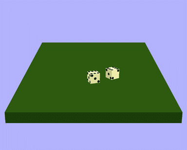
Figure 1-2. Communicative intent: show location of dice.
We will identify some of the basic things we can do in a visual presentation and some of the ways these things are accomplished. We will also specify when and why we might want to do these things. For instance, when we draw a map to show a friend how to get to our house there are some things that we will do which are similar to what someone else might do when drawing a picture to show how to turn on a stove. Both drawings may include visual effects. Some of the objects may be highlighted to show importance, an arrow may be used to show the way, and labels may be placed near objects to identify them.
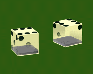
Figure 1-3. Communicative intent: show location of weights in loaded dice.
There are things that we can do in any visual presentation, in any visual language. These things are basic and verge on the universal. Some of these things can be done with words. For example, we can represent or refer to objects [Witttgenstein 58] and we can represent the same thing differently [Goody 87]. Both realistic and iconographic representation provides a one-to-one correspondence between the object and graphic. A metonymic representation uses a graphic of only part of the object to refer to the entire object. An associational representation uses a graphic of one object to refer to another object. The graphics used range from formalized conventions or symbols to arbitrary or abstract representations.
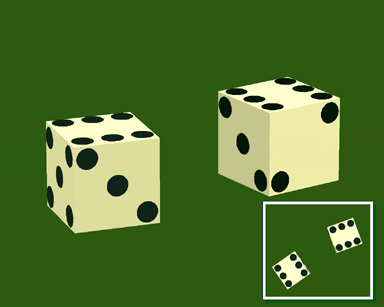
Figure 1-4. Communicative intent: show dice and value of “roll”.
Among the most basic and straightforward things we can do in a visual language is to show things pictorially. For example, we can identify things (like the house in a map, the outer edge of a cube); we can show movement (like a blurred object or an arrow); we can draw attention to something (like the face in a portrait or the only person in an empty field).
There are also very basic things we do to draw a picture. We draw lines, make marks, color areas, draw shapes and so on [Dondis 89]. These primitives are grouped together and applied by higher-level primitives that are also available in standard 3D graphics libraries. For example, to depict an object we group the primitives that together call the rendering instructions for that object. We can highlight an object by depicting it differently, or by changing all the rendering instructions for that group of primitives.
Similarly, there are certain conditions on which the success of these things is based. These conditions are basic and again verge on the universal. For example, for something to be shown successfully it must be seen and understood or recognized. In order for something to appear highlighted, it must appear different from the other objects and it must also appear different from how it would appear were it not modified.
In order to communicate effectively, not only is it imperative to know when and what to communicate; but it is also important, once this is determined, to know how to communicate. Knowing how to communicate is a matter of knowing how to use language well. Knowing how to communicate visually is matter of knowing how to use visual language well. We communicate successfully using visual materials all the time in our daily life, although most of us did not learn to do so by studying the grammar or usage of visual languages in school in the same way that we learned verbal language. To be sure, the first human languages (cave drawings, hieroglyphics, ideograms) are visual languages. Technical and engineering drawing, because they follow rules for composition, projection, and line styles, can be considered to be formalized visual languages. But, in what language are the illustrations in a VCR manual or the illustrations in a children’s book? Does every type of map have its own language, or do all maps share characteristics with all visual languages, but follow different conventions? They can all be considered to be expressions in different visual languages that share certain characteristics. We will not address the psychological, linguistic, philosophical, or anthropological issues concerning visual communication, skirting perception theory and semiotics. Instead, our approach is functional: every decision is made to solve the communicative intent, and our visual language is represented as collections of ways to accomplish goals.
“Style is a replication of patterning, whether in human behavior or in the artifacts produced by human behavior, that results from a series of choices made within some set of constraints.” [Meyer 87, p.21] We define all decisions effected during the creation of visual material as ones of stylistic choice. Thus stylistic choice refers to the procedures or way things are done as opposed to their end results. We would describe the style of a piece of art by the steps that are taken to create it rather than a description of how it looks. Stylistic choice encompasses both high-level and low-level decisions. In illustration, stylistic choices range from what objects to include to how each mark is drawn. A stylistic choice may determine how values are plotted on a graph, how nodes are aligned in a diagram, the colors used to fill in a label, the level of detail used to render a 3D surface, the choice of line weights, the combination of fully shaded graphics with line drawings, the lighting used and so on. Every procedure that is called upon when the visual presentation is generated is considered to be an application of particular stylistic choice. For example, the stylistic choices that comprise a Michelin road map range from what objects to show (e.g., lakes, roads, scenic views) to how each is rendered (e.g., blue areas represent lakes, red lines represent national roads, three line icons represents scenic views).
A false implication is produced when communicative material inadvertently implies something that is false. Avoiding false implicatures, is a very difficult problem in pictorial generation just as it is in natural language generation [Marks and Reiter 90]. Suppose that a knowledge base indicates that there are a dog and spotted cat on the mat under the bed. We wish to convey to the audience that “the cat is on the mat” and at the same time wish to avoid introducing extraneous information. If we generate the sentence, “The cat is on the mat.” we have not necessarily introduced any false implicatures by leaving out the fact that there also is a dog on the mat, or that the mat is large, or that the cat is white with brown spots, or that the mat, cat and dog are all under the bed.
One natural correlation to make is that between the objects appearing in the visual presentation (particularly if we consider 3D shaded color presentations) and the objects in real world as we see them. A picture of the cat on the mat, showing the whole mat with no other objects would be misleading. While we could generate a drawing that does not show the color of the cat, we may still have to include the contours of its spots to avoid the false implication it did not have spots. In order to differentiate the mat from a pattern on the floor, we may have to depict the texture of the mat. If the dog is left out of the scene, then the false implication is that the cat is alone on the mat; adding in the dog introduces extraneous information, but avoids a false implicature. But, most problematic of all, is the issue of the bed. Our system has to decide whether or not to include the bed. Not doing so may imply it is not there; yet by including it, we may completely obscure the cat, the mat, and the dog. If we decide to include the bed, then we have to render it so that the mat and cat and dog are visible, but in some way that does not falsely imply that the bed is not there. One solution is to choose a view specification in which only the cat and mat are clearly recognizable and only portions of the dog and bed are shown and thus may not be recognizable. Appropriate lighting can be used so that it is neither implied or apparent that the cat did not have spots. All of these methods apply illustrative techniques, or graphical devices used to create visual effects. In this example, the illustrative techniques are used to de-emphasize those properties that are not among the things we wish to convey, but at the same time do not introduce false implicatures.
The goal of knowledge-based graphics systems is to get some point across—to communicate effectively. A good presentation is clear, understandable, and informative; it is not confusing and provides straightforward correlations between the objects in the illustration and concepts in the real world which they were designed to represent. In order to achieve this goal, extraneous information is not introduced unnecessarily while certain objects, relations, or attributes are included if their omission may introduce further ambiguities or confusion. The procedures used to generate good presentations automatically therefore single out the salient features of the communication as well as the auxiliary features that are necessary to complement and complete the presentation. One way to address this problem, which is the approach we take, is to make each addition to the illustration one motivated by the specified communicative intent. This way, nothing is added without a reason.
This leads us to one interesting aspect of the problem of evaluating visual presentations—all constraints are global. Every element in a visual presentation may affect every other element in the presentation and in doing so, compromise its effectiveness to provide the proper visual cues. It is necessary to evaluate how the visual presentation looks to determine whether or not visual cues are effective. This can be approximated by examining the values of each pixel or by applying analytic methods that compute the value of certain relations without actually generating the presentation. For example, if the success of a particular visual cue depends on the legibility of an object, then the legibility of that object must be evaluated in order to determine the visual cue’s success. This must be accomplished in context of the entire illustration. The object may meet all legibility constraints in isolation, yet given the objects that surround it (or even obscure it), the object may not, in fact, be legible (as, for example, a white object on a white background).
Every element in the illustration may be interpreted to have some semantic value or to refer to something, either in the real world, to concepts or even to elements in other illustrations. For example, some icons and 3D shaded objects, as well as the slices of a pie chart are analogical; labels and arrows are symbolic. The color red may be interpreted to mean “hot,” exaggerations may be interpreted to mean “a lot.” In order to generate effective presentations, systems require knowledge related to the semantics of the objects being depicted (as they are known by the viewer) and the semantics of the graphical objects (as they will be interpreted by the viewer) that appear in the visual presentation.
Another concern is determining when a presentation violates the stated intention. How can this be accomplished? We could ask the viewer what he or she interpreted the presentation to signify and check if this corresponds to the intention. Many graphics systems rely on users to adjust the specifications to arrive at a solution that corresponds to his or her intent. Alternatively we can incorporate rules that apply simple checks on a presentation to determine if the interpretation will match the intent. Such rules depend upon knowledge to evaluate how certain graphical devices will be interpreted. This, at first, may seem like an impossible task, and that would be true if we were to attempt to consider all aspects of human interpretation. But, by limiting ourselves to certain aspects of interpretation, based on well-founded rules governing visual perception, and formalisms concerning the use of visual languages, we may approach satisfactory solutions.
This thesis makes four main contributions. We first provide a brief description for each. The sections that follow describe them in greater detail.
• Visual Language for 3D Worlds: The Primitives and Rules We present a visual language that is defined by a collection of primitives and the rules for their usage. We define three types of primitives: communicative goals, style strategies and illustration procedures. Communicative goals describe what it is we can express; style strategies describe the visual effects and cues we use in an illustration; illustration procedures describe the ways we change the values of every parameter that defines a picture. For example, one communicative goal is to show an object’s location; a style strategy that helps satisfy this communicative goal is to highlight an object, and an illustration procedure that can be used to highlight an object is to increase its lighting. Design rules map communicative goals to style strategies. Style rules map style strategies to illustration procedures. For example, a design rule for showing an object’s location specifies that, among other things, the object should be highlighted. A style rule for highlighting an object, specifies a set of illustration procedures that increase the lighting of an object (while another specifies to outline the object). Similarly, we define two types of rules: methods specify how to accomplish a goal, evaluators specify how to determine how well a goal has been achieved. Thus, the visual language we define is made up of an alphabet of illustration procedures, a lexicon of style strategies, a grammar for communicative goals, and syntax and semantics defined by design and style rules.
• Methodology and Architecture for Illustration We introduce an illustration process that involves two types of stylistic choices: the choice of different designs to achieve communicative goals, and the choice of different styles to achieve design goals. We have implemented IBIS as proof-of-concept of our ideas. Our system consists of three main components: illustrators use design rules to achieve and evaluate communicative intent; drafters use style rules to achieve and evaluate designs; the illustration contains the set of procedures that alter and examine the actual computer graphic picture. The illustration process entails the selection of methods and application of evaluators in order to determine if partial solutions are successful. If conflicts occur, the system backtracks and alternative methods are applied. Throughout this thesis we show examples of the illustrations IBIS generates for several different domains and applications.
• Composite Illustrations In some cases, communicative intent may be as difficult to achieve in one illustration as it is to achieve in a single sentence. For example, the communicative intent may be to show the opposite sides of the same object, or to show parts of an object in great detail, but also in context of a much larger object, both of which must appear in the illustration. No one view can satisfy both these constraints. We define a composite illustration as a set of related illustrations which in concert fulfill the intention of the communication and provide mechanisms to generate composite illustrations when goals cannot be achieved in one illustration. Our system determines that the communicative intent cannot be satisfied in one illustration and opts to generate a composite illustration. Composite illustrations are generated by a hierarchy of illustrators. We show how IBIS generates series and insets.
• Interactive Illustrations The relationship between the various components and the illustration remain dynamic, even after a solution has been found. The methodology we present depends upon a trial-and-error approach, during which the illustration is continuously modified and then reevaluated. This mechanism is used to support different types of interaction. We demonstrate four ways interaction is used to enhance communication. First, we show how IBIS allows the user to interact directly with the system, by moving about in the illustrated environment. Second, we show how the objects that are depicted may be moving about and changing state. Third, we show how the goals associated with an illustration can change due to the direct interaction with external modules or when the system determines that the communicative intent is no longer valid. Fourth, we show how the mechanisms for self-evaluation can be called by external modules.
We define three different levels of representation for an illustration. These correspond to the three types of primitives that define the visual language: communicative goals, style strategies, and illustration procedures. Design rules map communicative goals to style strategies while style rules map style strategies to illustration procedures. Figure 1-5 shows the primitive and rules of the visual language.
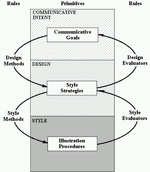
Figure 1-5. The Visual Language.
Communicative goals range from those that specify the concept that is to be conveyed to the user to those that actively aid the user to do something. Figure 1-6 shows the list of communicative goals we have implemented. Figures 1-1 through 1-4 show examples of three different communicative goals. The communicative goal show is
achieved by presenting the user with an understandable depiction of an object. All four of these figures can be said to “show the dice.” The communicative goal location is satisfied by depicting an object so that its position with regard to a context object is depicted. Figure 1-2 shows the dice in context of the table, Figure 1-3 shows the weights in context of each die. The communicative goal property is to show the value of an object’s property. Figure 1-4 shows the value of the property ”roll” of the dice.
show show the object
identify show the object’s identity
reference refer to the object
state show the object in a particular state
change show the change in an object’s
state
action get the user to perform an action
location show an object’s location in
some context
relative-location show the relative positions
of two or more objects
property show the value of object’s property
The style strategies define the visual cues that are introduced into a illustration to achieve communicative goals. Figure 1-7 shows the list of the style strategy goals.
include represent the object
visible ensure that the object appears in the
illustration
recognizable ensure that the object is recognizable
highlight highlight the object
focus focus on the object
subdue subdue the object
find get the user to locate the object
visual-property ensure that the property is
shown
move show movement with an animated arrow
label label the object
ghost create a ghosted image of the object
context include context objects
meta-object create an annotative object
In Figures 1-1 through 1-4 the dice are included, visible, and recognizable. In Figure 1-3 the weights are also included, visible, and recognizable. In Figure 1-3 the weights are highlighted; they are distinguished by being the subject of a ghosted cutaway view.
In order to both execute style strategies and test their success, the illustration is manipulated directly. Evaluation procedures perform tests on the current state of the computer graphic picture to determine the value of certain properties. One such procedure determines what objects occlude a specific object. Other procedures are used to accomplish styles. For example, the procedures to generate a cutaway view involve direct manipulation of the frame-buffer and z-buffer.
Design rules describe how communicative goals are achieved by style strategies; style rules describe how style strategies are achieved by illustration procedures. While design rules describe the overall plan of an illustration or what visual cues are used, style rules describe how each individual visual cue is executed. However, not only is it necessary to represent how to achieve goals, it is also necessary to determine when goals are violated. Design rules also describe what collection of visual cues achieve communicative goals, and thereby provide the means to evaluate how well a communicative goal is accomplished. Style rules also describe the criteria by which a visual effect is evaluated as successful by performing a series of tests on the illustration. This duality is represented by two kinds of rules. Methods specify how to achieve goals; evaluators specify how to determine a goal’s success. For every style strategy and communicative goal there must exist at least one method and evaluator. The body of design rules consists of design methods and design evaluators; the body of style rules consists of style methods and style evaluators.
Work in natural language generation addresses the problem of automatically generating text to achieve communicative goals. We adopt in spirit the model that distinguishes content planning and surface generation [McKeown 85] in natural language generation for illustration generation. Selecting designs is analogous to content planning, while selecting styles is analogous to surface generation. However, some of the problems encountered when dealing with visual material are different from those in natural language. For each decision made, each time the illustration is altered any number of goals may be negatively affected. This is the nature of a visual presentation. If we add an object to an illustration or change the way it is rendered we may jeopardize the success of every other visual cue in the illustration.
An intent-based approach enables the system to illustrate the same world differently, based not only on the state of the world but also on what it is that is to be conveyed about that world. The criteria used to make stylistic choice are based on the desired semantics of the illustration. Each method is tried to achieve a specific communicative goal. Our architecture supports mechanisms both to detect conflicts and replan, as well as to handle overly constrained problems. The overall design is separated from individual style choices, as is the process to select designs and styles. The effectiveness of an illustration is affected by the interplay between visual effects and the actual characteristics of each object in the illustration. For example, it might be appropriate to highlight an object by brightening it if all other objects will appear darker, or it might be more effective to darken the object if all the other objects will appear lighter. This style decision is separate from the decision to highlight the object in the first place and the way it is achieved need not be determined at the same time.
Human illustrators plan and replan an illustration, considering at all times how the final illustration will look. An illustrator may try something on paper and then, after evaluating it, erase it and adopt another plan. Alternatively, the illustrator may be so skilled that it is enough for him or her simply to imagine the consequences of a stylistic choice. This characterization of illustration serves as the foundation for our approach to intent-based illustration. Using the system of methods and evaluators a generate-and-test approach can be used. When evaluations return failure, the system can backtrack to try alternative methods.
There are three main active components in our architecture. Illustrators select the designs of the illustration, while drafters select the styles. The illustration itself is a dynamic object that includes the methods to accomplish and evaluate visual cues.
Figure 1-8 shows the illustration process. The system has access to a knowledge-base describing the world (not shown). An illustrator is assigned a set of communicative goals. For each of these communicative goals, the illustrator selects a design method from its design rule base. A design rule specifies a prioritized set of style strategies that are assigned to a drafter. For each one of these style strategies, the drafter selects a style method from its style rule base. A style method calls illustration procedures that directly access and modify the illustrations. As the illustration is modified, evaluators that correspond to active goals are activated. As long as all the goals are satisfied the illustration remains in its current state; however, if a goal is evaluated to fail, the system backtracks and alternative methods are activated.
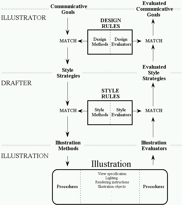
Figure 1-8. Illustration process.
Our methodology depends on a mixture of general and specialized knowledge. The procedure that was applied to ghost away the parts of the dice to reveal the weights in Figure 1-3 determined what objects occluded the weights using the object list and z-buffer. It was not necessary to provide this information in the object representation, instead it was determined during the illustration process. However, the knowledge that is used to ensure that the spots on the dice are legible so that the dice are recognizable is object-specific and is part of the object representation for every die.
Other types of specialized knowledge are used to activate different methods when appropriate. For instance, the rule to show the “roll” of the dice, as shown in Figure 1-4, can only be activated when the dice come to a rest. A concept-specific rule was introduced to detect when the rest state is reached while another specialized rule to depict the faces of the dice in order to show the property “roll.”
Sometimes one illustration alone cannot effectively satisfy communicative intent. A composite illustration is a set of illustrations that in concert satisfy communicative intent. There are several conditions for which a composite illustration is generated. An illustration may be overly constrained, as when, for example, the goal is to show the fine print on two very distant objects. No single view exists that can accommodate this goal. The communicative intent may be to show a series of complex steps that cannot be depicted adequately in just one illustration. Rules partition the communicative goals into sets that are assigned to different illustrators to achieve. The components of a composite illustration are arranged in a hierarchy. A separate illustrator is responsible for each component of the composite illustration, but subordinate illustrators are governed by their parents, and a master illustrator is at the root of the hierarchy. Figure 1-9 depicts the hierarchy of the composite illustration of Figure 1-3 whose goals are to show the dice and show the property “roll.”
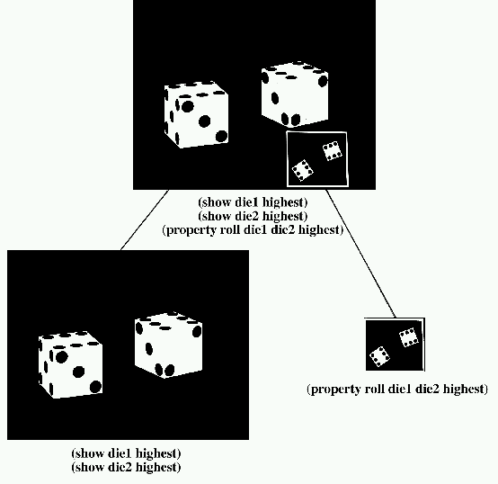
Figure 1-9. Illustrator Hierarchy.
Communicative intent: show the dice, property “roll” of the dice
During the design process, illustrations remain bound to their illustrators and drafters. This dynamic relation need not terminate when the communicative intent is achieved. We make possible interactive intent-based illustrations by keeping the illustrators and drafters on call to satisfy communicative intent continuously as the situation and circumstances change.
The user can move about in the illustrated environment in two distinct ways. As the KARMA user, who is wearing a head-mounted see-through display, moves about in the real world, his or her view of the world is monitored. When viewing graphics presented on a high-resolution display, the COMET user can navigate using a mouse-based user-interface. In both cases, the user-determined view specification is treated as a constraint. As the view specification is changed, goals may be violated. The illustrators and drafters continuously adjust and modify the illustration so that the communicative goals remain successful. For example, the intent may be to show an object. The style strategy goal, visible, is employed to show the object. As the user navigates, the object may be obscured by other objects. In order to maintain the object’s visibility a graphical device such as a cutaway view is generated to reveal the object through the obscuring objects .
Figure 1-10 shows the illustration IBIS designs to maintain the visibility and recognizability of both dice during user-navigation. The user has zoomed in on one die which triggers a failing evaluation for the other die’s visibility. Since the view specification is constrained by the user, the system must find an alternative method to show the other die. In this case, an inset illustration is generated to show both dice and thus successfully achieve the specified communicative intent.
The objects depicted can move in two ways. First, in KARMA, certain objects are equipped with sensors that track their movements. This information is used to evaluate the user’s actions. The representation of the tracked objects is altered to reflect how they move and determine their state. Second, this mechanism can be adapted to handle changes caused by a simulator.
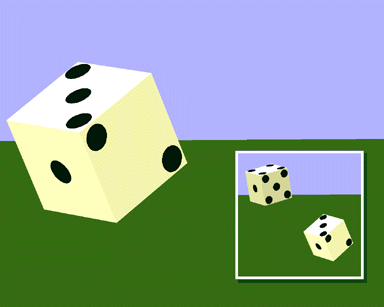
Figure 1-10. Automatically generated inset during user-navigation.
Communicative intent: show the dice
Rarely are visual presentations shown in isolation. Consequently, systems that generate visual matter should provide facilities to communicate with the various components of a multimedia system. These facilities correspond exactly to the three classes of primitives of our visual language.
Before we describe the interaction needs of a multimedia system, let us consider the architecture of one multimedia system, COMET [Feiner and McKeown 90, Feiner and McKeown 91], for which IBIS generates graphics. A module called a content planner [McKeown et al. 90] determines what should be communicated. This is specified using a logical form [Allen 87]. For every medium, there is a media generator. For example, FUF [Elhadad 91, Elhadad 93] is the text generator and IBIS is the graphics generator. Another module, called the media-coordinator, determines what parts of the logical form should be handled by different combinations of media generators. The media-coordinator annotates the logical form with these assignments and all media generators share the annotated logical form [Elhadad et al. 89].
Certain things are expressed more effectively in one medium than in another. The appropriateness of one medium over another is a factor of the communication itself, the context, and situation. Assignment of communicative goals can therefore fail; a generator may not be able to satisfy the goals it has been assigned. The media coordinator should be able to reassign goals amongst the generators. To enable negotiation between the various media generators, we believe that each media generator should be able to provide an assessment of how well it can achieve communicative goals. Our architecture enables this sort of evaluation easily. An illustrator can be called upon to evaluate communicative goals, a drafter can be called to evaluate style strategy goals, and the illustration procedures can be called upon to determine the value of different attributes. The queries need not be limited to those currently active. For instance, the illustrator may be asked to evaluate how well an object’s location is shown in an illustration designed to show how the object is manipulated. This mechanism is useful when a media generator is assigned a communicative goal but cannot accomplish it. The media-coordinator can call for evaluations from the other media generators for that goal. Using this new information, the media-coordinator can determine whether or not the multimedia communication, as a whole, adequately satisfies this goal. Thus, unnecessary changes can be avoided.
Similarly, each media generator should be able to describe the stylistic choices used in its solutions. This enables the various media generators to refer to each other’s stylistic devices. For example, COMET’s text generator can produce cross-references, referring to the visual cues used by the graphics generator [McKeown et al. 92] such as “the object that appears in the cutaway view,” or “the highlighted object in the inset.” A graphics generator therefore should be able to represent the visual cues in its illustration so that other modules can produce the descriptions and references. Again, our architecture meets these demands. All decisions can be recorded, identifying the goals and the methods used to accomplish them.
It is also necessary to be able to refer to the individual elements and symbols in a communication. This mechanism is necessary to ensure consistency between the various components of the multimedia communication. For example, a text generator may generate text that refers to an object as “the white knob on the left” because using the world model, the knob is white and to the left. But, the graphics generator designed an illustration in which the knob is colored red, labeled as the “channel-dial,” and appears in the right portion of the illustration. All of this information is available through the illustration procedures and can be used to better coordinate the text and graphics and can be used by the text generator to refer to the object in a manner that corresponds to its depiction in the illustration.
It may be appropriate to change goals due to the user’s actions, changes in the world, or simply the passage of time. Goals may be introduced, removed, or their importance may change. If the communicative intent is to get the user to perform some action, then that goal’s success is dependent upon the user’s actions. In this case, once the user performs the task, the goal is accomplished and becomes obsolete. Illustrations may be evaluated as successful, while the user’s actions indicate they are not successful [McKeown et al. 92]. For example, a user is presented with an illustration that is evaluated to successfully convey an object’s location. The user, however, continuously queries the system for the object’s location. Our system is augmented with specialized rules to support different types of interaction. In this case, the illustration is modified to provide additional visual cues to show the object’s location.
We use communicative intent to describe the purpose and desired function of the communicative material. We describe communicative material as the result of stylistic choice and thus formalize the generation of communicative material as sets of procedures. The process itself is goal-driven and decomposed into the three levels represented by the visual language we present: communicative goals, style strategies, and illustration procedures. Because all constraints in visual material are global we determine that it is necessary that for every method to accomplish a goal, there must exist at least one evaluator to judge that goal’s success given the current state of the illustration. The visual language includes design rules (to map communicative goals to style strategies) and style rules (to map style strategies to illustration procedures). These rules fall into one of two categories: methods describe how to accomplish a goal, evaluators specify how to judge a goal’s success. Thus the visual language defines the rules and primitives. The methodology and architecture define how these rules are applied by the three active components (illustrator, drafter, illustration). A communicative intent may be impossible to satisfy in just one illustration, composite illustrations provide a handy mechanism for such overly constrained problems. Interaction with the user enhances communication. We define four forms of interaction that are supported by our architecture: user-navigation, changing worlds, changing goals, and self-evaluation.
Technological advancements make it possible to develop radically different systems for communication, including systems that will be able to automatically generate customized communicative material in an interactive setting. These systems will be based on general rules of language and interpretation. This thesis describes a system for visual communication. Such a system has a potentially enormously wide application since computer systems typically use visual displays to interact with users. Multimedia systems pose new problems in coordination and synchronization. The system presented in this thesis is designed to address some of these problems.
In Chapter 2 we describe related work, providing the reader with a framework by which to compare this work to others. In Chapter 3 we describe our methodology for intent-based illustration and detail the architecture. We show the object representation and rules and show how they were used by the various components to generate one illustration. In Chapter 4 we introduce our visual language, describing the primitives we implemented for COMET. In Chapter 5 we show how we generate composite illustrations. In Chapter 6 we describe the four modes of interactivity, and how the architecture is modified to support each. In Chapter 7 we describe how our system is modified to support new functionality, new output devices, new objects, and new concepts. In particular we describe the modifications in the architecture and new rules that were introduced for KARMA. In Chapter 8 we summarize the results of this research and describe future directions.