Weibin Zhao
zwb@cs.columbia.edu
Ying Zhamg
yzha@cs.columbia.edu
Abstract
This project implements an Internet Telephony Gateway. First, it construct a driver that interface the Teltone T-311 telephone access unit. Second, it act as a bidirection gateway between packet (Internet) telephony and PSTN, allowing dial-in and dial-out.
Introduction
Internet Telephony is an emerging technique for making phone call by computer network. It has some advantages over traditional PSTN, such as cost effective for long distance call. The connection between computer network and PSTN is performed by Internet Telephony Gateway. It includes hardware connection, software processing of audio packets, and phone call control. In our implementation, hardware connection is through Teltone T-311, audio packets processing and call control is done by Gateway software.
This report will give a detail descriptions of the whole project. First, we will give a brief review of related works, and some background information. Second, we will outline our architecture, including design goals, hardware connection and software relations; Third, we will describe detail design of each part, and some implementation notes; Fourth, we will describe our program documentation, includes: installation instruction, and operation user guide; At last, we will give out system measurements steps and contents, future work consideration for improvement, system deliverable, task list, and references.
Internet Telephony Gateway is a hot topic in today's computer network. Many researches and implementations have been done on it. Currently we have a device called Teltone T-311 telephone access unit which can connect analog phone line to standard computer sound card and RS-232 serial port. We have a Windows version software package (CommLynx) that controls T-311. Our purpose is to implement the basic interface to T-311 in Sun Solaris environment, and provide Internet Telephony Gateway service.
First, we need give brief introduction to Teltone T-311. T-311 is communication device similar to a modem that enable computer to communication through telephone line. While a modem only transmits data from computer to computer over telephone lines, T-311 provides more control functions and allows communication between called and calling parties. The communication is made possible by conversion of DTMF-to-ASCII and ASCII-to-DTMF. DTMF is stands for Dual-Tone MultiFrequency (pushbutton telephone signaling). T-311 uses the industry-standard AT command set. It responds to commands and call processing events by sending message to the computer.
With T-311, computers are easy to control telephone system functions, such as outgoing calls control, incoming calls control, and security control for incoming calls.
2. Hardware Connection:Provide a generic interface to T-311 that support all its commands issue and status display, like a unix tip command. Input is performed in standard mode, not in raw mode, this will facilitates command line edit and modification. Simplify user commands that interface to gateway. Although user can use original T-311 commands, but it is not easy for a beginner to learn the complex syntax. Instead, we provide a rather simple interface for user to make a phone call and answer a phone call. The required T-311 command sequence is performed automatically by client software and gateway server. Minimize gateway processing overhead to reduce voice latency.
For detail connection instruction, please see [2] Figure 3.connect T-311 with computer: for control signal, connect T-311 "RS-232-C" with one of computer serial ports; for voice data, connect T-311 "REMOTE" to linein and lineout of workstation's soundcard. connect T-311 with telephone line: connect T-311 "LINE" to one of telephone jack. power on T-311: connect T-311 "INPUT POWER PACK" to power outlet by a power transformer.
3. Software Architecture:
Using client-server model. Gateway server is located at a dedicated workstation (in our configuration, bourbon.cs.columbia.edu) which is connected to T-311 by RS-232-C and soundcard linein/lineout. Gateway client can be used at any Solaris workstation. When making an outgoing call, gateway client will contact getaway server. If line is not busy, call proceeds. When there is an incoming call, gateway server will notify corresponding gateway client. If call is accepted, then call proceed, otherwise hang-up.
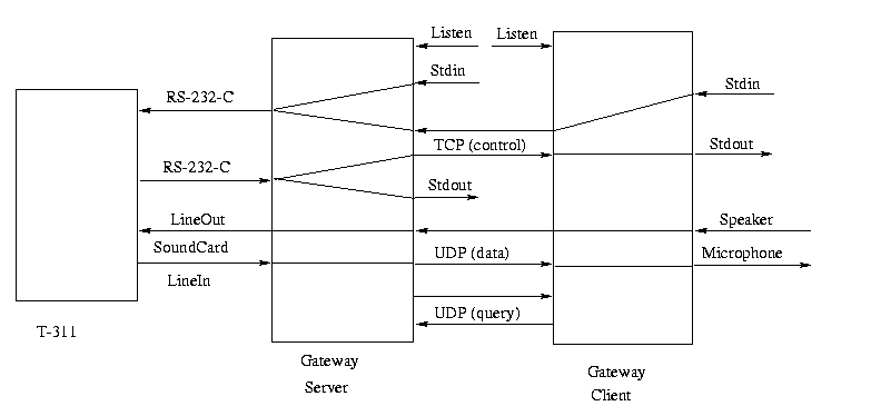
There are many communication channels between gateway server and gateway client, as well as between T-311 and gateway server. Some channels are used for control information, some channels are used for voice data transmission. Figure 1 gives channels connection.
Figure 1. Channels Connection
RS-232-C is a duplex channel, transfer T-311 commands from gateway server
to T-311, and transfer T-311 status information from T-311 to gateway server.
Soundcard Linein is used for transmitting voice packets from T-311
to gateway server, while soundcard Lineout is used for voice packets transmission
in the opposite direction.
TCP channel is used for setting up call, call control and call termination. UDP (data) channel is used for for voice data transmission. Additional UDP (query) channel is used for line busy query and reply. Moreover gateway server and client has listen channel which wait for peer party connection. When an incoming call is arrived, gateway server initiate a TCP connection to corresponding client; Similarly, gateway client initiate a TCP connection when user want to make a phone call through gateway server.
Gateway server and client also has local input and output.
Detail DesignFor gateway server, it has stdin and stdout. It accept user commands from stdin, and display T-311 status to stdout. For gateway client, it also has stdin and stdout. It accept user commands from stdin, and display T-311 status to stdout. For voice data, it accept input from microphone, and send output to speaker.
There are basic two type of message flows in the system, one is call control message, the other one is voice data message. Call control messages are transmitted through TCP channel for reliability, while voice data messages are transmitted through UDP channels for real-time requirement.
1. Gateway Server:
When started, gateway server does following initializations:
Gateway server includes two processes, one is event-driven I/O multiplexing input process by "select" mechanism, the other one is child process of previous process, that read packets from soundcard linein and send them to corresponding client at a constant rate (8 KB/Second). Child process is enabled and disabled by its parent process. That is, when a phone call is initiated, enable child process; when a phone call is finished, disable child process.Initial RS-232 serial port. Open audio device with linein and lineout as voice data input and output. Create a TCP socket, listen for client connection. Create a UDP socket, for voice packets transmission with client. Create another UDP socket, for client line-busy query and reply.
Gateway server works in two modes: one is local commands mode, the other one is remote commands mode. Local commands mode is defined as T-311 commands come from local stdin, while remote commands mode is defined as T-311 commands come from client.
Gateway server is mainly used as message a router. It read message from several sources, and forward these messages to the proper destinations. Next we give a list of message routing:
Apart from forwarding messages, gateway server also perform important control functions:Read commands form local stdin, analysis, and send T-311 commands to serial port. Read T-311 commands from TCP channel (come from client), forward to serial port. Read serial port (T-311 status information), send to local stdout. If it is in remote commands mode, these packets also need send to TCP channel (to client). Read audio device linein, send to voice data UDP channel (to client). Read from voice data UDP (from client), send to audio device lineout. Read from inquiry UDP (from client), analysis, send proper information to reply UDP (to client) indicate whether phone line is busy or not. Read from listen port, if line not busy, accept new TCP connection.
2. Gateway Client:Create TCP connection: when there is an incoming call, mapping email address or phone number to IP address by directory service, initiate TCP connection to corresponding client. Terminate TCP connection: (1) when client has closed peer connection; (2) when incoming call has been rejected by client; (3) when telephone user types "*#" command to instruct server to hang-up; (4) when server detects "NO ACTIVITY" time out. Accept TCP connection: when phone line is not busy, accept new outgoing call request. Automatic incoming call answer:(1) there is a "RING" incoming call message from T-311, answer the call with "ata" command; (2) there is a "ANSWERED" message, enable audio device lineout with "at*r2" command; (3) there is a "OK" message, play welcome message to calling party. Each step above has a unique state number, in order to differentiate with similar message, for examples, "OK" message has been used for all successful operations. Automatic outgoing call enable: when client request an outgoing call and phone line is successfully seized, enable audio device lineout. Directory service: mapping email address or phone number to IP address. Audio sender enable: (1) when incoming call is accepted by client; (2) when outgoing call successfully seizes the phone line.
Client components:open audio device with microphone and speaker as voice data input and output. (Note: gateway client and server use different audio device I/O port, as audio device can only has ONE input port enable, so client and server must be located at different machines) Open a TCP socket, listen for server connection. Open a UDP socket, used for voice data transmission with server. Open another UDP socket, used for line-busy query and reply.
It also consists of two processes, parent process for event-driven multiplexing input, child process for constant rate audio data sender, read from microphone and send to gateway server. Child process sending function is enabled and disabled by parent process.Client message flows
Client control function:Read commands from local stdin, analysis, and send to TCP channel (to server). Read voice data from local microphone, send to voice data UDP (to server). Read from voice date UDP (from server), send voice data to local speaker. Read from TCP channel (from server), display T-311 status in local stdout. Send line busy inquiry through inquiry UDP (to server), and receive reply from server. Read from listen port, accept server connection.
Implementation NotesCreate TCP connection: when there is an outgoing call request, first check whether the phone line busy or not, if not busy, initiate TCP connection to server. Terminate TCP connection: (1) when server has closed peer connection (passive). (2) when user issues "bye" command (active). Accept TCP connection: when there is an incoming call. Audio sender enable: (1) when accepts an incoming call. (2) when there is an outgoing call, and phone line is not busy.
1. System Requirements:
2. Software:two Sun Ultra1 workstations running Solaris, with standard audio device: microphone, speaker, linein. lineout, etc. Teltone T-311 telephone access unit, and necessary cables: RS-232-C, audio cable. one telephone jack, assigned one phone number for T-311, another normal telephone has a phone number different from gateway server.
DocumentationIt is written in C language, about 1000 lines of source code. Communication is implemented mainly on top of socket API. RS-232 driver code is mainly borrowed from [1], some necessary modifications are made.
Installation includes five steps: connect hardware, install gateway
server, install gateway client,
setup environmental variable GATEWAY_DIR and GATEWAY_ADDR, test whole
system.
If you need the source code package, you can also get it for system deliverable.connect hardware: see Hardware Connection. install gateway server: get server.tar.gz from system deliverable, copy to a directory, and gzip -d server.tar.gz, tar xvf server.tar, then you will have the following files: 311s, ds, welcome.au, sorry.au, README.server. Be sure to include the this directory in your PATH. "311s" is the gateway server; "ds" is the mapping file for directory service; "welcome.au" is the audio file for welcome message; "sorry.au" is the audio file for failure phone call message; "README.server" is instruction file for installation. install gateway client: get client.tar.gz from system deliverable, copy to a directory, and gzip -d client.tar.gz, tar xvf client.tar, then you will have the following files: 311c, ring.au, README.client. Also, be sure to include this directory in your PATH. "311c" is the gateway client; "ring.au" is the audio file for phone ring message; "README.client" is instruction file for installation. setup GATEWAY_DIR: make it refer to your installing directory; setup GATEWAY_ADDR in each client: make it refer to the IP address of gateway server. test system by making an incoming call and outgoing call.
T-311 has several LED in its front panel. "POWER" (green) and "DATA
TERM. READY" (red)
should always on. "LINE STATUS" should be off if the phone line if
on-hook, on if phone line off-hook. When there are control messages transmitted
to/from T-311, the "RECEIVE DATA" and "TRANSMIT DATA" should flash.
Gateway server operations:
Basic T-311 commands:Start gateway server with: 311s port_number Gateway server will use port_number, and port_number+1 for TCP and UDP communication, be sure not to conflict with other systems (in general port_number should > 10000) Notify all clients that your server is ready, tell them your server IP address and port number. When server started properly, it should display:
- Welcome to Internet Telephony Gateway Server
- output_port = 4 input_port = 2
You can type all T-311 commands from stdin to setup and control T-311. When you want to shutdown the gateway server, use "quit" command.
To assist you learn T-311 commands quickly, we give a brief introduction here:
Important Notes:First, it use standard AT commands set, each command begins with "at" (case insensitive). To call a number: atdxxxx To hang-up: ath To answer a call: ata To initialize: atz To display version information: ati To enable lineout: at*r2 To display status register: atsxx? To modify status register: atsxx=xx
MeasurementsStart gateway client with: 311c port_number Be sure to use the same port number as the gateway server. When client started properly, it should display:
- Welcome to Internet Telephony Gateway Client
- output_port = 1 input_port = 1
- Usage instruction:
- To make a call, use: call phone_num
- To end a call, use: bye
- To see this message, use: help
- Thank you.
To make a phone call, use command: call phone_number To end a phone call, use command: bye To exit client, use command quit. In general, what you need to make a phone call through gateway server is "call" and "bye". However, if you like, you can type any T-311 commands between "call" and "bye". If there is an incoming call for you, you will hear a short music, and a piece of message that tell you a phone call is coming, requests to you select answer ot not (y/n), if you type "y", then you can talk with calling party, otherwise, the call is rejected.
1. Call Control Tests:
Incoming call tests:
Task ListGateway server package. Gateway client package Source code package. Source code directory. Project initial design report. Project final report (This file). Demo Slides (PostScripts).
This project is design and implemented by Weibin Zhao, tested by Weibin
Zhao and Ying Zhang.
Thanks to Prof. Henning for providing many help.
[1] W. Richard Stevens, Advanced Programming in the UNIX Environment,
Addison-Wesley, 1992
[2] T-311 Telephone Access Unit Reference Manual, Teltone, 1995
[3] CommLynx User Manual, Teltone