Nirav A. Vasa
Department of Computer Science
Columbia University
New York, NY 10027
USA
nav2109@columbia.edu
We describe how to use a laser pointer and a camera to emulate a mouse, allowing a presenter to control a computer remotely during a presentation. The utility of this system would be in a large classroom environment or a presentation where an instructor or presenter can simply use the laser pointer and move the mouse on the projected screen without using the computer mouse. To move the mouse to a particular position on the screen, the user just needs to point the laser at that particular position and that does the job. The laser pointer can also be used to emulate mouse clicks by turning the laser off and on at the same position on the screen. The main advantage of this system would be in a large classroom environment where an instructor is moving around in the class and presenting something on a computer screen (say a power point presentation) projected by means of a projector. The instructor does not at every instant need to go to the computer mouse and change the slides; rather he can just use this software and can emulate a mouse (motion and clicks) by the use of just a simple laser pointer.
Consider a large room where a PowerPoint presentation is being made using a projector. The presenter normally uses a laser pointer to point on to the screen to some details in the current slide. But imagine if the presenter could also be able to change the slide using the same laser pointer and also the presenter could also be able to do other activities like switch windows, open a new application etc, which he wouldn't be able to do otherwise. This could be realized if the laser pointer is somehow used as a device which would be able to emulate the mouse on the screen. This idea gives rise to this project where we design an implement a simple tool which could generate mouse events by detecting a laser pointer on the screen.
The basic idea of the operation of this tool is to capture the image of the projected screen using a camera and then in this captured image, we detect the laser pointer and identify its corresponding position on the projected screen and move the mouse accordingly The tool is designed to work on Microsoft’s windows operating system.
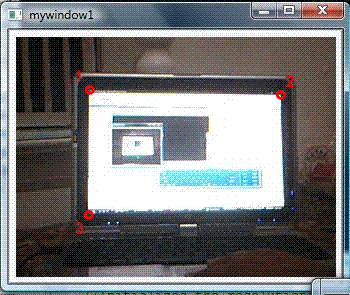
The tool runs in two main stages namely, Initialization and Detection. In an ideal situation, the camera would be able to see only the projected screen and thus, the corners of the image created by the camera would co inside with the corners of the projected screen. Thus, just detecting the laser pointer and scaling the image to the actual resolution of the screen would be enough to calculate the corresponding mouse position on the screen. But this does not happen in actuality. The camera does not see only the projected screen; it also sees the surrounding background with it. Thus, it becomes necessary to input into the system the position of four corners of the projected screen on the captured image so that the program can calculate the position of the mouse. Calculations of the position of the mouse pointer are made based on these four corner points. This is done in the initialization stage. This calibration is done by showing the user an image of the screen captured by the camera. The user clicks on the four corners of the screen in the image and these coordinates are saved by our program as the four corners of the screen and all the further calculations of the mouse pointer are made using these coordinates as reference points.
After the initialization the camera starts capturing the image of the projected screen and passes this image to the image processing module. The laser detection module checks the image received from the camera for the presence of a laser point. Depending upon the presence or the absence of the laser various decisions of moving the mouse or performing clicks are taken which is explained in detail using the state transition diagram.
Camera images are captured and processed using Intel's opencv library. It has a camera interface which is used to capture camera images and it has several functions to extract pixel information from the images.
The program enters the initialization phase when first run. Here, user is asked to input the four corners of the screen in the projected image. Once the four corners of the rectangular screen are input by the user, they are used as the reference points in all the further calculations of the mouse pointer locations.
The images are first captured by the camera and displayed on the screen at regular intervals (video) which allows the user to adjust the camera in such a way that the whole of the projected screen is seen in the image captured by the camera. Once the camera is properly positioned, the user presses a key to get a still image of the current screen. On this still image, the user clicks on the four corners of the screen and these clicks are recorded by the program and stored as the four corners. After the user clicks on the four corners, the escape button on the keyboard is pressed, which completes this stage and the program now goes into the detection stage.
The actual working of the program takes place in the detection phase which is followed by the initialization stage, where the four corners of the projected screen are input by the user. Now the program knows the four corners of the screen. The program now captures the images from the camera at regular interval and processes these images to detect the position of the laser in the image. This function is performed by the laser detection module. After the laser pointer is detected in the image, the coordinate of the point is given to the transformation module which transforms the position of the laser dot on the screen to its corresponding coordinates on the computer screen.
Intel's opencv library is used for capturing the image from the camera. If no camera is connected or, if the program isn't able to detect the camera, an error message is displayed on the screen. If the camera is detected, it is used to capture images of the screen.
After the Image has been captured, the image is passed to the laser detecting module. This module detects the presence of the laser dot on the image if any and on successful detection, it returns the position of the laser pointer in the image.
Laser detection algorithm : We work on the basis that the laser is supposed to be the brightest red point in the whole image. We than extract the RGB values of all the pixels in the image (using the get2D ( ) function provided by the opencv library) and compare those values with a predetermined threshold values. All the pixels which have their RGB values in the acceptable range are then considered and their x and y co-ordinates are then averaged, which gives us the approximate position of the laser dot on the screen. This algorithm would work in an ideal situation but there are various problems associated with it which can be solved using the following approaches.
Over Exposure - Due to excessive light entering the camera lens, the camera isn't able to distinguish the laser dot from the other parts of the screen. As a result, the above algorithm fails as, even the pixels other than the ones comprising of the laser dot would be above the threshold value and thus, would skew the results. To avoid this, various approaches could be taken. We reduced the brightness and exposure settings of the camera and also used a gray filter which is fixed in front of the camera lens to reduce the intensity of the light entering the camera lens. These approaches make the laser dot more distinguishable from the background screen pixels and thus, allow the successful operation of the algorithm.
Jerkiness - Another problem that is associated with the detection technique is that the user's hand is not always steady and tends to have a bit of jerkiness. Due to this the laser dot on the screen also keeps on having the jerkiness on the projected screen. Thus, the calculated mouse pointer coordinates keep on changing from the previous value only by a small value which leads to a very small mouse motion on the screen in a jerky manner. This is not a desired effect and thus, to get rid of this effect we check the difference of the current calculated pixel position value from the previous one and if that difference is within a certain range, 'R', it is assumed that the difference is due to the jerk effect and not due to actual motion of the laser dot. If this is the case, the motion is not taken into account and the position of the mouse pointer is not updated because of that motion of the laser pointer. We also use this same range 'R' in deciding clicks. To emulate clicks, the laser pointer needs to be turned off and then on again at the same position. It is very difficult to turn off the laser pointer and back on at exactly the same position. Thus, we check if the laser pointer is turned back on in a certain range, again 'R', we assume it to be a click, or else we assume that it’s just a mouse movement.
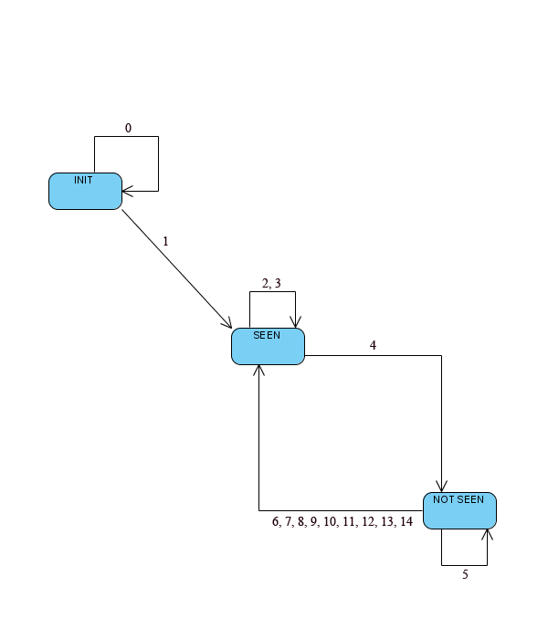
False offs - As discussed earlier, the mouse activities that are emulated are "mouse_move", "left_button_down" and "left_button_up". There are three possible states in which the system can be in namely "INIT", "SEEN" and "NOT_SEEN". INIT is when the program has started but hasn't detected a laser dot yet in any of the images. Once the system detects a laser dot in one of the images it goes into the "SEEN" state. Now, depending upon whether the laser dot is detected or not detected, the state of the program changes to "SEEN" or "NOT_SEEN" respectively. That said, the problem of false offs is that, in some images, though the laser dot is present, the algorithm fails to detect it because it does not cross the threshold value, maybe because of external background effect and the quality of the camera. This leads to false transitions to the "NOT_SEEN" state and leads to unwanted "left_button_down" action being emulated (Refer to the state transition diagram, in section 5 for more details). To solve this problem, we classify the off type depending upon the amount of time the off was seen. We select an upper and a lower limit for an off to be qualified for a click. If the off last for a time smaller then the lower limit, its considered to be a false off and is ignored. If the off lasts for a time longer then the upper limit, it is considered as a delayed off and is not considered as a click as well. Instead, in both the cases, the mouse is moved to the position corresponding to the position of the laser pointer when seen after the off. If the off duration falls in the range of the thresholds, it’s assumed to be a true off and a left_button_down action is performed if it was not down previously, else, left_button_up action is performed. This successfully emulates clicks.
If the laser dot is detected, the program gives the co-ordinates of this detected laser dot to the transformation module. The function of this module is to calculate the position of the mouse pointer on the screen corresponding to the current position of the laser dot in the image being processed. The position is calculated in terms of the fractional distance of the position of the pointer from the left edge of the screen (fraction of the width of the screen) which when multiplied with the width of the screen gives the x co-ordinate of the point and the fractional distance of the position of the pointer from the top edge of the screen (fraction of the height of the screen) which when multiplied with the height of the screen gives the y co-ordinate of the point.
This is implemented in a slightly different manner as compared to the method explained in [1]. In this case, we assume the image of the projected screen to be a perfect parallelogram. This assumption makes the calculations used in the whole process of transformation of the co-ordinates slightly simpler but slightly compromises on the accuracy of the calculations. The following paragraph explains the whole process.

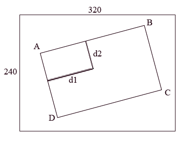
Figure 1 - Sample transformation from a captured image.
Consider the diagram shown above. We consider points A, B, C, D as the four corners of the screen. The user needs to input only three corners into the program during the initialization stage namely the top left, the top right and the bottom left (A, B, D). Our assumption that the screen is viewable as a parallelogram can be used to calculate the 4th point, the bottom right one easily. Now assume X is the position of the laser pointer detected by the laser detecting module. We then calculate the distances of this particular point X from the left edge of the screen and call this distance as d1 and from the top edge of the screen and call this distance as d2. We then use these distances d1 and d2 respectively to find out the actual mouse position on the screen in the following way. We first calculate the length of the left edge of the screen. In this diagram, this can be depicted by the distance AD. We also calculate the length of the top edge of the screen, which can be seen from the diagram as the distance AB. We also have the distances d1 and d2 as mentioned earlier. Using these distances we calculate the fractional position of the point on the screen.
Fractional horizontal distance = AB/d1
Fractional vertical distance = AD/d2.
The windows mouse API allows us to use these fractional horizontal and vertical distances to specify the position of the mouse pointer. The function mouse_event provided by the windows API takes in these fractions multiplied by 65535 as input and moves the mouse accordingly on the screen using these values.
The program emulates three main mouse activities "mouse_move", "left_button_down" and "left_button_up". There are various events which lead to these activities which are explained in detail in the state transition diagram.
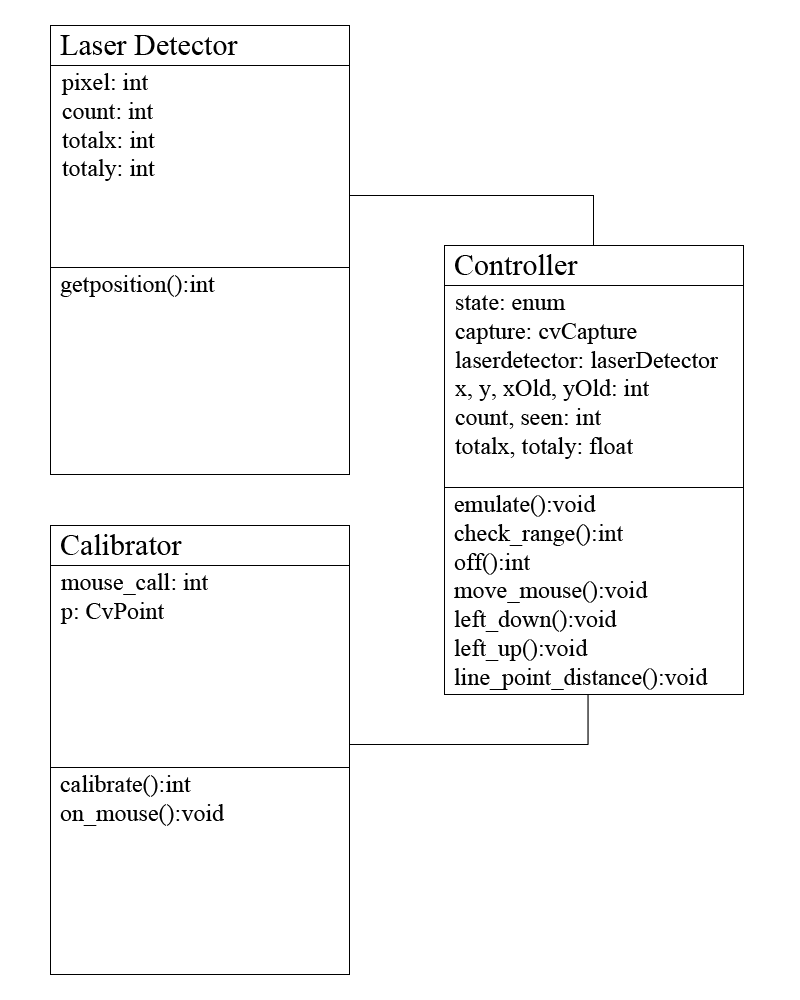
We have an object oriented design with a class structure with methods and variables. The main idea behind designing the modules is to separate the methods used for performing the two stages.


Figure 1 - State transition diagram.
The above diagram represents the transitions between various stages that the system makes because of the occurrence of certain events. The following text explains what these events are. Events are indexed according to the numbers in the diagram.
Variables:
ld = true if left mouse button is already down, else false.
range = true if current laser position is within the range 'R' as explained above, else false
seen = true if the laser pointer is seen in the current capture, else false
ot = off type... 0->false off , 1->true off, 2->delayed off (Depending upon what kind of off it is, the value 0, 1 or 2 is returned accordingly)
States:
INIT = start state
SEEN = seen state
NOT_SEEN = not seen state
Transitions:
The following table explains the transitions between various states and the conditions which lead to those transitions and the actions that are carried out during those transitions. This state machine is capable of handling mouse motion and clicks.
ID |
From |
To |
Condition |
Action |
|---|---|---|---|---|
0 |
INIT |
INIT |
(!seen) |
- |
Remain in the init state until laser pointer is first seen. |
||||
1 |
INIT |
SEEN |
(seen) |
(move_mouse(xNew, yNew)) |
Go to seen state after seeing the laser pointer for the first time. Move the mouse to the point where the laser pointer is currently seen. |
||||
2 |
SEEN |
SEEN |
(seen , !range , !ld) |
(move_mouse(xNew, yNew)) |
Stay in seen state and move the mouse pointer at the point where the laser pointer is currently seen. |
||||
3 |
SEEN |
SEEN |
(seen , !range , ld) |
(move_mouse(xNew, yNew)) |
This will occur, when the left button is down. This implements the drag behavior. |
||||
4 |
SEEN |
NOT_SEEN |
|
- |
When the laser pointer is not visible go to the not_seen state and do nothing with the mouse pointer. |
||||
5 |
NOT_SEEN |
NOT_SEEN |
(!seen) |
- |
Stay in the not_seen state. Update the count variable for not seen. This variable is used to decide, which kind of off is it (false/true/delayed). |
||||
6 |
NOT_SEEN |
SEEN |
(seen , range , ld , ot=0) |
- |
It is a false off. Also, the laser pointer is now seen at a point which is not outside the range of motion. Hence do nothing, just move to seen state and let the left button be still down. |
||||
|
NOT_SEEN |
SEEN |
(seen , range , !ld , ot=0) |
- |
Again the same reasoning as 6, except the left button is not down. |
||||
8 |
NOT_SEEN |
SEEN |
(seen , !range , ld , ot=0) |
(move_mouse(xNew, yNew)) |
False off, but the laser pointer is now seen outside the range of motion, hence just move the mouse to the new point. Let the left button still be down. |
||||
9 |
NOT_SEEN |
SEEN |
(seen , !range , !ld , ot=0) |
(move_mouse(xNew, yNew)) |
Again the same reasoning as 8, except the left button is not down. |
||||
10 |
NOT_SEEN |
SEEN |
(seen , range , ld , ot=1) |
(left_up(xOld, yOld)) , ld=0 |
Its a true off, within the range, that means, we need to emulate a click at the original position of the mouse pointer, where it first became invisible. Also, the left button was already down, so we do a left button up action and change the value of ld to 0 to indicate that the left button is up now, that means a click is complete. |
||||
11 |
NOT_SEEN |
SEEN |
(seen , range , !ld , ot=1) |
(left_doown(xOld, yold)) , ld=1 |
Its a true off, within the range, that means, we need to emulate a click at the original position of the mouse pointer, where it first became invisible. Also, the left button was initially up, so we do a left button down action and change the value of ld to 1 to indicate that the left button is down now, that means a click is complete.
|
||||
12 |
NOT_SEEN |
SEEN |
(seen , !range , ld , ot=1) |
(move_mouse(xNew, yNew)) |
Its a true off, but its seen outside the range of the previous seen position, thus, it is not taken as a part of a click, just the mouse is moved to that the newly seen coordinates. |
||||
13 |
NOT_SEEN |
SEEN |
(seen , !range , !ld , ot=1) |
(move_mouse(xNew, yNew)) |
Its a true off, but its seen outside the range of the previous seen position, thus, it is not taken as a part of a click, just the mouse is moved to that the newly seen coordinates. |
||||
14 |
NOT_SEEN |
SEEN |
(seen, ot=2) |
(mouse_move(xNew, yNew)) |
Its a delayed off, just move the mouse to the new position corresponding to the laser pointer's position. |
||||
Click here for detailed instructions on compiling and downloading the project files.
Running the program
