The Forgers
CS-6998 - 3D Photography - Fall 02
Team members: Alexei Masterov - David Smilowitz - Alejandro Troccoli - Sam Neymotin
|
|
|
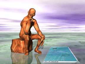
In this step we perform the model-to-image(s) registration.
Problem Statement
Given a 3D model of the statue find rotation, translation and camera projection parameters that map 3D points to 2D image coordinates. Assume a pinhole camera model.
Approach Taken
We used the original raw range data to perform model-to-texture registration. The input to our program that computed the transform was the point cloud produced by the laser scanner in the cyclone "ptx" format, which is an ascii file that contains 3D coordinates of all points in the scanner coordinate frame. This was necessary because the original scans contained the features around the statue which were used for the registration (The statue itself contained very few easily identifyable features).
A user manually selects a set of corresponding points from the point cloud and the 2D image which are used to compute a projection matrix
that transforms world coordinates to image coordinates. The method for computing
be a pair of 3D and 2D homogeneous point correspondences, with
and
of the form
and
respectively. Each pair provides the following two equations,
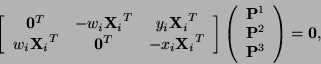
where eachis a row of
pairs, a
matrix is obtained
. The solution vector
of the set of equations
contains the entries of the matrix
and
respectively. Once the projection matrix
where each
is a mesh triangle is computed. The function evalutes to
when
otherwise. At this point the mesh is textured by calculating the texture coordinats of every visible triangle.
Procedure
The program displays the range data and the image side-by-side using the OpenGL renderer.The user selects the points in the image and the corresponding points in the model using the mouse:
After the minimum of 6 constraints were added the program produces the transform.
Then user may render the mesh with the texture applied to evaluate the transform:
If the mapping is not satifactory, user may choose to start the process over or add more constrains to refine the transform. Once the mapping is satisfactory it is only left to compute the transform between camera position and the model coordinate frame. We achive this by composing the transform that represents the camera position in relation to a given point cloud with the transform that maps that point cloud to the model coordinate frame. (which we obtained in the global registration phase). More on this in part 4 of this report.
Additional Considerations
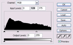
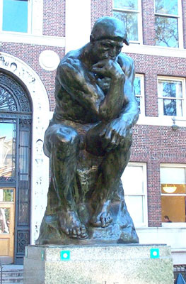
We used Kodak DC280 digital camera which is a consumer digital camera with practicaly no manual settings, therefore we had to post process the digital images to extract the maximum color information from the surface of the statue.
g |
 |
 |
|
Figure 3-3: Captured images were manually adjusted with an image processing program to extract more color information. (left: original image, center: level adjustment dialog, right: image with levels adjusted. |
There are few things to be done here to improve the results. 1. It would be better to use camera with manual settings for aperture and exposure. 2. before appying more than one texture on a model one should normalize all textures with respect to one another.
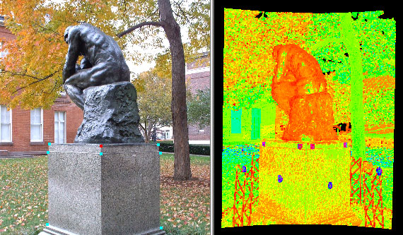
Results
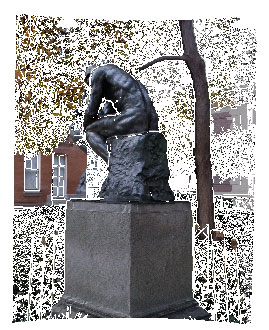
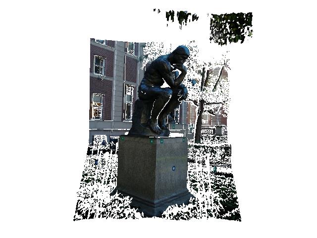
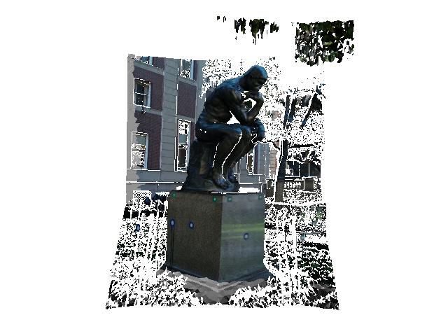
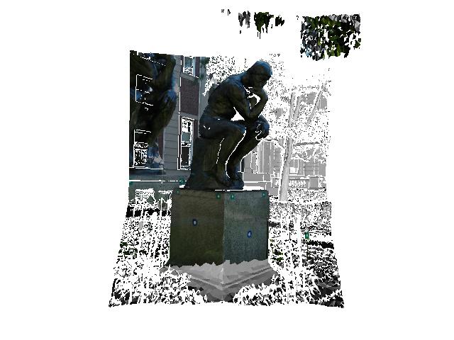
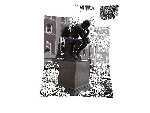
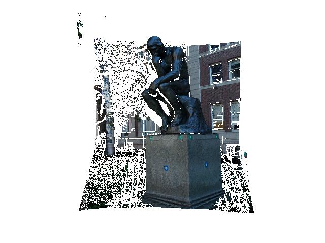
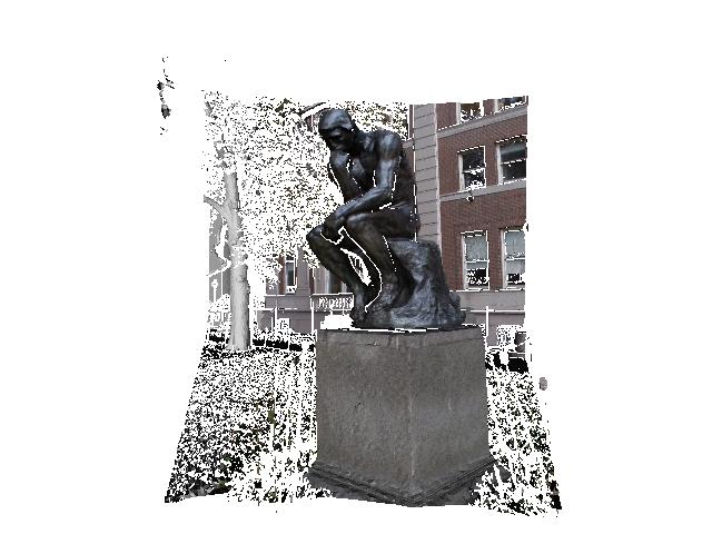
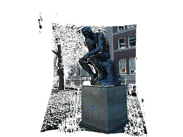
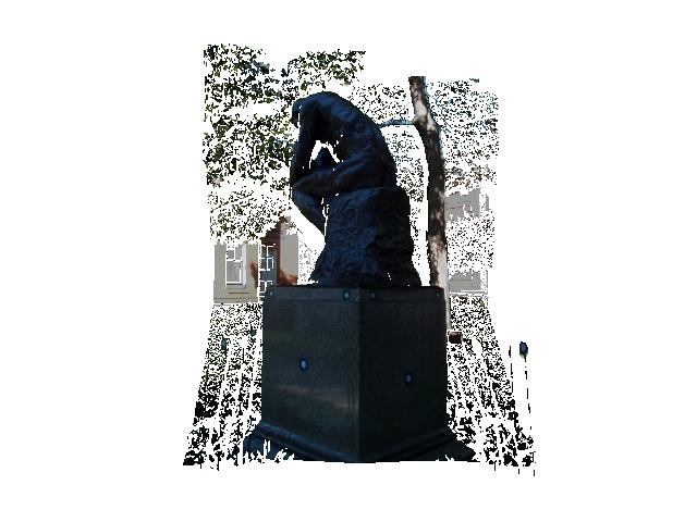
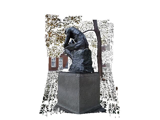
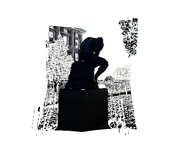
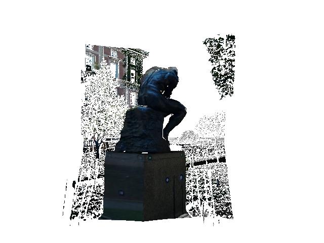
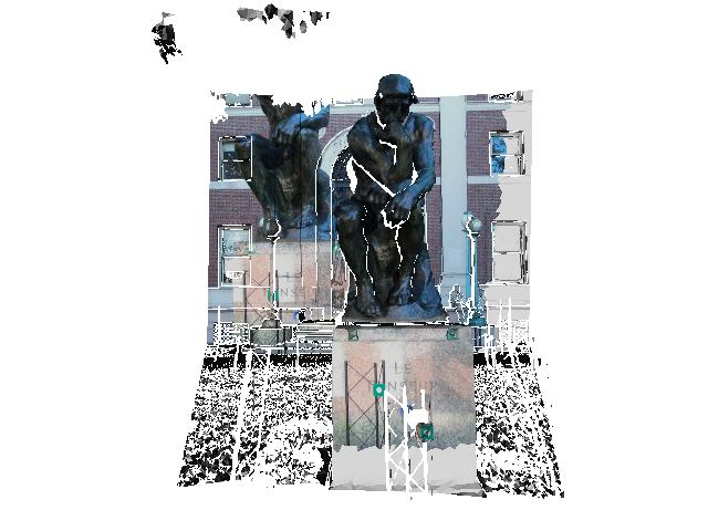
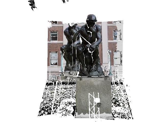
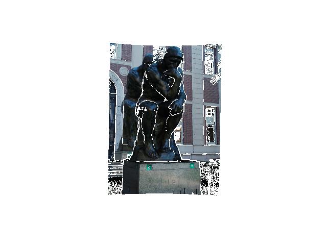
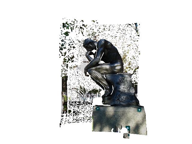
Here we show the result of the model to image registration for different meshes. There are two approaches for achieving model to image registration: the first one is to register each image with respect to the complete integrated surface; the second one, on the other hand, is to register each image with respect to the individual scans and then, by using the approapiate transforms, map the texture to the integrated surface. We chosed the latter method motivated by two reasons. Firslty, most of our images weere taken close to the scanner position for a given scan. And second, our individual scans have additional background details which our integrated mesh does not have. This additional background provides details that we can use as constraints during for the registration.
.
mesh1_img002.jpg
mesh1_img008.jpg
mesh1_img015.jpg
mesh1_img040.jpg
mesh2_img005.jpg
mesh2_img039.jpg
mesh2_img11.jpg
mesh3_img12.jpg
mesh3_img042.jpg
mesh4_img003.jpg
msh4_img041.jpg
mesh5_img006ls.jpg
mesh5_img38.jpg
mesh7_img007.jpg
mesh7_img16.jpg